Load-Transient Response & Voltage Stability
Engineering Solutions: Load-Transient Response & Voltage Stability
A practical engineering guide to stabilize DC-DC load steps by balancing inductance retention L(I), DCR voltage sag, thermal headroom (Irms), and saturation margin (Isat). Includes platform comparison across ferrite, molded metal-composite, and flat-wire designs.
Fast load steps (high di/dt) are a top root cause of voltage droop, resets, and instability in automotive ECUs, ADAS sensor rails, and industrial control power stages. This hub explains the physics and provides an “overall operating margin” method to select the most stable inductor platform.
- Load-transient instability happens when output current changes rapidly (high di/dt), causing voltage droop or overshoot.
- Typical symptoms: brown-out, ECU/MCU reset, sensor dropout, unstable rail during boot-up or mode switching.
- Core reason: transient events push the inductor close to its real operating limits—L(I) drop, DCR sag, and thermal stress.
- L(I) retention under peak current determines whether the inductor can still buffer energy.
- DCR determines the instant resistive sag during surge current.
- Irms defines thermal headroom (how hard you are driving the part continuously).
- Isat defines saturation headroom (how close you are to collapse during peaks).
- ΔV ≈ L(I) · (di/dt) + I · DCR
- L(I) = effective inductance at operating current (drops as current rises)
- di/dt = current slew rate during load step
- DCR = DC resistance (creates instant voltage sag and heat)
- Inductance collapse: when L(I) drops sharply at high current, energy buffering disappears during peaks.
- Resistive sag: when DCR is high, Vout sags immediately during surge current (ΔV = I · DCR).
| Application | Transient source | What goes wrong |
|---|---|---|
| Automotive ECU / control modules | motor start, injector firing, mode switching | reset, CAN errors, unstable rail |
| ADAS camera / radar / sensors | SoC boot-up, AI workload steps, link activity changes | sensor dropout, image glitch, unstable output |
| Industrial PLC / automation rails | I/O switching, servo events, load distribution changes | control instability, intermittent faults |
- Transient stability must be judged by overall operating margin: L(I) retention + DCR sag + Irms thermal headroom + Isat saturation margin.
Why this matters
- During a 2× load step (e.g., 10A → 20A), the inductor must keep enough L(I) to remain an effective energy buffer.
- Ferrite designs can show a cliff-like inductance drop near saturation, which increases droop/overshoot risk.
Estimated inductance retention
| Technology / Series | Inductance retention @ 10A | Inductance retention @ 20A | Engineering note |
|---|---|---|---|
| SDS127H (Ferrite, shielded wire) | ~80–85% (drop ~15–20%) | ~0% (collapse) | High risk under 2× peaks |
| SEP1206A (Flat-wire shielded, ferrite behavior) | ~80–83% (drop ~17–20%) | ~0% (collapse) | Low DCR, but watch saturation collapse |
| SEP1206E (Molded metal-composite) | ~89–90% (drop ~10–11%) | ~70% (drop ~30%) | Soft-saturation maintains usable L(I) |
| SEP1010EXM (Flat-wire metal-composite) | ~90–92% (drop ~8–10%) | ~67–68% (drop ~32–33%) | Best peak-current inductance stability |

Text formula
- Instant voltage sag: ΔV = I · DCR
- At the same current, halving DCR roughly halves the instant sag.
10A reference comparison (your dataset)
| Series | DCR | ΔV @ 10A | Meaning |
|---|---|---|---|
| SDS127H | 21.5 mΩ | 215 mV | Largest resistive sag |
| SEP1206E | 10.0 mΩ | 100 mV | Best for low sag |
| SEP1206A | 10.5 mΩ | 105 mV | Low sag, but check L(I) collapse at peaks |
| SEP1010EXM | 13.7 mΩ | 137 mV | Slightly higher sag, strong overall headroom |

- Lowest DCR does not automatically mean the best transient stability.
- Engineers need a combined view: resistive sag (DCR) + thermal headroom (Irms) + saturation margin (Isat / L(I)).
| Series | ΔV @ 10A | Thermal load (10A / Irms) | Saturation load (10A / Isat) | Conclusion |
|---|---|---|---|---|
| SDS127H (Ferrite) | 215 mV | 165% (over-limit risk) | 89% (near edge) | Legacy option, not recommended for harsh transients |
| SEP1206E (Molded) | 100 mV | 100% (nominal) | 64% (stable) | Balanced stability + low sag |
| SEP1206A (Flat-wire) | 105 mV | 95% (nominal) | 105% (saturation risk) | Great sag performance, but watch 2× peak collapse |
| SEP1010EXM (Ultimate) | 137 mV | 64% (high headroom) | 57% (high headroom) | Best overall operating margin & reliability |
- Transient stability should be selected by overall operating margin, not “DCR only”.
- Thermal headroom: higher Irms capability (lower 10A/Irms ratio)
- Saturation margin: higher Isat + stable L(I) under peak current
- Low DCR performance: smaller instant sag at surge current
- Compact size: higher power density / footprint efficiency
Platform mapping for load-transient stability
| Engineering goal | Recommended platform | Why it works |
|---|---|---|
| Keep inductance under 2× peak current | SEP (metal-composite molded), SEP-EXM (metal-composite flat-wire) | Soft saturation keeps usable L(I) during peak events |
| Minimize instant droop (low sag) | SEP, SEP-A, SEP-EXM | Lower DCR reduces ΔV = I · DCR during surge |
| Best overall reliability under harsh transients | SEP-EXM | Best combined thermal + saturation headroom (operating margin) |
| Cost-sensitive / legacy rails | SDS (shielded ferrite wire-wound) | Suitable when peak current is controlled and transient severity is low |

- Related Products
10uH, 14.6A SMD Molded Flat Wire Inductor
SEP1010EX-100M-LF
Composite High Current Molded Flat Wire Power Inductors with flat cooper wire, SEP1010EX series (10mm height), which offers high current handling capacity,...
Details Add to List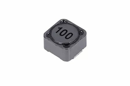
10uH 11.2A High Efficiency Inductor with dimension 12*12*7mm
SDS127H-100M-LF
10uH 11.2A Wirewound Surface mount Shielded Inductor with dimension 12*12*7mm, a compact powerhouse engineered for high performance and reliability in your...
Details Add to List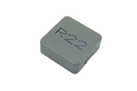
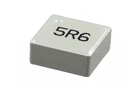
10uH, 15.5A Composite High Current Shielded Power Inductors
SEP1206E-100M-LF
The demand for the composite high current shielded power inductors is changing to compact designs that are power efficient. The molded SMD power chokes...
Details Add to List- Related FAQ
For ECU DC-DC converters, Isat should be evaluated under actual operating conditions, including elevated ambient temperature and self-heating caused by load current. Datasheet values measured at room temperature...
Read moreDC resistance (DCR) directly influences conduction losses in power inductors. Higher DCR results in increased heat generation under load, which can raise component temperature and accelerate long-term...
Read moreDC bias affects effective inductance under load. In automotive systems operating continuously at elevated temperatures, insufficient DC bias margin can lead to reduced efficiency or unstable power regulation.
Read more