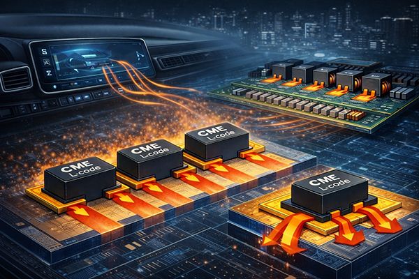
Thermal Management & Power Density (EV Compute & AI Server VRM)
Engineering Solutions: Thermal Management & Power Density — Power-Dense Rails Without Thermal Runaway
A practical engineering guide to keep EV compute and AI server VRM power rails cool by balancing I²·DCR loss, Irms thermal headroom, copper geometry (flat vs round), and PCB heat spreading through terminal pad contact. Includes a 10A ΔT evidence table and a VRM clarification box: “400A ≠ single inductor”.
High-current rails in EV compute modules (ADAS / cockpit SoCs) and AI server VRMs push extreme current density in compact, low-airflow environments. The real limit is often thermal margin—not a single datasheet current number. This hub shows how to evaluate power density using measured temperature rise (ΔT), copper geometry, and PCB heat spreading through pad contact area, then maps the right platform to each design target.
Thermal Margin Sets the Real Current Limit
- In compact modules with limited airflow, inductors can become a dominant heat source.
- Thermal margin is driven by heat generation (I²·DCR + AC loss + core loss) and heat escape (terminals/pads → PCB copper planes).
- Use measured ΔT under the same condition to reveal real platform differences.
| What engineers want | What to check |
|---|---|
| Lower hotspot risk | ΔT evidence + terminal/pad conduction path |
| Higher power density | Irms headroom + PCB heat spreading area |
| Stable operation at high switching frequency | Copper geometry (flat vs round) + AC loss tendency |
Flat Copper vs. Round Wire — Why Geometry Changes ΔT
- Flat copper often improves power density because it spreads current and heat more effectively and can reduce high-frequency copper loss penalties.
- Round wire more easily concentrates heat near the winding/core region, increasing hotspot risk in low-airflow environments.
| Conductor | Thermal intuition | High-frequency intuition |
|---|---|---|
| Flat copper | More surface/contact coupling → better heat spreading | Often lower skin/proximity penalty than round wire |
| Round wire | More localized heat → higher hotspot risk | More sensitive to skin/proximity effects as frequency rises |

Data Evidence: 10A Temperature Rise (Same Ambient, No Airflow)
Test condition: 10A, room temperature +25°C, no air flow, same condition across samples.
| Part / Structure | DCR | Irms | Test current | ΔT | Notes |
|---|---|---|---|---|---|
| SEP1206E (Round-wire metal composite) | 10.0 mΩ | 10.0 A | 10A | +40°C | Room Temp +25°C, No air flow |
| SEP1206A (Ferrite wire-wound shielded, Flat wire) | 10.5 mΩ | 10.5 A | 10A | +22°C | Same condition |
| SEP1010EXM (Flat-wire metal composite) | 13.7 mΩ | 15.5 A | 10A | +18°C | Same condition |
| SDS127H (Ferrite wire-wound shielded, Round wire) | 21.5 mΩ | 6.04 A | 10A | +80°C | Same condition |
- What this shows: At the same current and environment, platform structure can create a 4× ΔT gap (hotspot/thermal path differences).
PCB Heat Spreading: Recommended Pad Contact Area (Single Pad)
Pad sizes below are recommended single-pad dimensions. Actual thermal performance also depends on PCB copper planes and whether terminals/bottom pads are flattened for conduction.
| Platform | Recommended pad (mm) | Single-pad area (mm²) | Heat-spreading note |
|---|---|---|---|
| SEP1206E | 4.5 × 4.5 | 20.25 | Moderate conduction area; PCB copper becomes important |
| SEP1206A | 5.0 × 5.25 | 26.25 | Larger pad helps reduce thermal resistance to board |
| SEP1010EXM | 11.0 × 3.4 | 37.40 | Large conduction area supports higher power density |
| SDS127H | 5.4 × 2.8 | 15.12 | Smaller area tends to trap heat; board design is critical |
Note: Pad size is not a direct proxy for copper thickness; some designs use flattened conductors or bottom pads to increase conduction.
“400A ≠ Single Inductor” — VRM Current Is a System Number
Important clarification: “400A-class” rails are system-level VRM currents, not a single-inductor rating.
- EV compute and AI server rails typically use multi-phase VRM architectures.
- Total load current is shared by many phases (e.g., 12–24 phases).
- Each phase inductor typically carries ~15–30A (design dependent), while the full rail sums to 300–600A+.
| Example | Typical math |
|---|---|
| 400A rail with 16 phases | Per-phase current ≈ 400A ÷ 16 ≈ 25A |
| 480A rail with 20 phases | Per-phase current ≈ 480A ÷ 20 ≈ 24A |
Selection focus should be per-phase thermal headroom, stable inductance under peak current, and low hotspot risk in low-airflow modules.
Thermal Escape Path: Terminals/Pads → PCB Copper Planes
- Most heat leaves the inductor through terminals and pads into PCB copper planes.
- Higher power density designs reduce hotspot formation and improve conduction into the board.
- Verification is simple: compare ΔT at the same current under the same airflow and PCB conditions.


Thermal-Optimized Platform Mapping (EV Compute & AI VRM)
| Design target | Recommended platform | Why it fits |
|---|---|---|
| Lowest ΔT and strongest per-phase thermal headroom | SEP1010EXM (flat-wire metal composite) | High Irms headroom + strong conduction area for power density |
| Best power density in compact modules | SEP1206A (flat-wire ferrite shielded) | Flat copper structure improves heat spreading in tight layouts |
| Balanced cost & temperature for general rails | SEP1206E (round-wire metal composite) | Metal-composite platform with practical thermal performance |
| Cost-sensitive / legacy rails (board-dependent) | SDS127H (round-wire ferrite shielded) | May require more PCB copper / airflow to avoid thermal runaway |
FAQ Snapshot: Thermal Reality Check for EV Compute & AI Server VRM Rails
Below are the three most relevant FAQs for Thermal Management & Power Density. These are written to match real system behavior in EV compute and AI server / data center VRM rails.
Q1: How does DCR affect thermal reliability in ECUs?
- DCR turns current into heat: copper loss is approximately P ≈ I2 · DCR. Small DCR differences become large temperature differences at high current.
- Heat accelerates aging: higher hotspot temperature increases stress on solder joints, insulation, and surrounding components—reducing long-term stability.
- Practical takeaway: don’t compare DCR alone—verify ΔT at the same current and confirm the PCB has enough copper plane to absorb heat through the pads.
Q2: Why datasheet current ratings may not reflect real ECU operating conditions?
- Datasheet conditions vary: airflow, PCB copper thickness, plane size, and ambient temperature can be very different from your module.
- System current is not single-part current: “400A-class” is typically a multi-phase VRM number; each phase inductor commonly handles ~15–30A depending on phase count and control strategy.
- Transient & thermal are linked: load steps raise peak current and heat simultaneously; if thermal headroom is small, the rail becomes unstable under real workloads.
- Practical takeaway: use Irms headroom + ΔT evidence as the decision anchor, not a single “current rating” line.
Q3: What factors should be taken into account when using power inductors with regard to thermal considerations?
| Thermal factor | What to check | Why it matters |
|---|---|---|
| I²·DCR loss | DCR at operating temperature | Primary heat source under DC load |
| Irms headroom | Operating Irms margin (not just peak) | Prevents thermal runaway in low-airflow modules |
| Pad conduction path | Pad area + copper planes + vias | Main heat escape route: terminals → PCB |
| Copper geometry | Flat vs round conductor structure | Influences hotspot formation and HF copper loss |
| Environment | Ambient, enclosure, airflow, adjacency | Defines the real thermal ceiling |
| Verification | ΔT at same current, same PCB condition | Fastest way to compare platforms fairly |
Bottom line: Thermal success in EV compute and AI VRM rails is a system outcome—choose the inductor platform using ΔT evidence, Irms margin, and PCB heat-spreading capability.
- Related Products
10uH, 25A SMD Molded Power Inductors
SEP1707EA-100M-LF
The best choice of the SMD high current molding power chokes for high efficiency power converter. The model of SEP1707EA, high efficiency fixed inductor...
Details Add to List
10uH 4.9A Compact Power Inductor – High Efficiency, Low Core Losses
SEP4020EMH-100M-LF
The SEP4020EMH series is a compact yet powerful flat-wire SMD inductor, delivering high current handling, low DCR, and superior shielding. With its 4.0 x 4.0 x 2.0mm...
Details Add to List
10uH, 4A Flat wire power inductor
SEP0605A-100M-LF
State-of-the-art SMD Flat Wire Power Inductor, a compact marvel engineered to elevate your designs to new heights. With dimensions of just 7.0x6.9x5.0,...
Details Add to List